

The purpose of the combination of multiple types of ARM processors in the TI chip is to allow all regular operations to be done by M4 and use A15 only for the compute-intensive operations. This allows us to use minimal power resources. Additionally, specific functions can be done through hardware itself instead of within processor.
This comment was marked helpful 0 times.
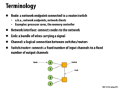

What is a good example of a channel? In the picture above, it seems to say that a connection between two switches/routers is a link, but the definition of a channel is a connection between switches/routers.
This comment was marked helpful 0 times.

@mitraraman The difference between a link and a channel is that a link is physical whereas a channel is logical. For example, lets say that there are 2 switches/routers (1,2,3) in the network where there are links between the pairs (1,2) and (2,3). One can say that there's a logical connection (channel) from 1 to 3 even though they're not directly connected.
This comment was marked helpful 4 times.
It's like how your computer is connection to some web server.
This comment was marked helpful 0 times.

Based on the context of the following slides where contention of switches are discussed, it seems the switches are only allowed to select one input and direct it to one output. Why can't we make the switches handling multiple inputs/outputs at the same time? Or is it just a cost/performance balance issue?
This comment was marked helpful 0 times.
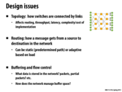

Topology examines how to arrange switches using links (i.e. it is the topological structure of the network).
Routing is the process of deciding the path that a message takes from a source to a destination in a network.
This comment was marked helpful 0 times.
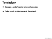
In interconnected networks, messages are the abstraction and packets are the implementation.
This comment was marked helpful 1 times.


Example of blocking vs. non-blocking: Consider 4 distinct nodes on a network, A, B, C, and D. Suppose that A wants to send a message to B, and C wants to send a message to D. In a non-blocking network, it would be possible for both of these messages to be sent at the same time. In a blocking network, it might not be possible for both of the messages to be sent at the same time. Perhaps both message routes share a switch that can only handle one message at a time.
This comment was marked helpful 0 times.

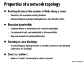
For bisection bandwidth, if the bandwidth is low, then there are not many links that cross between the two sides of the network, so contention will be high. If the bandwidth is high, there are many links crossing the two sides, so contention will be lower.
This comment was marked helpful 0 times.

For you nerds out there, a network would be blocking if the graph representing the network had a cutvertex.
Worst-case bisection bandwidth is almost k-connectivity.
This comment was marked helpful 0 times.

An example of non-blocking given during the review session is if you have two nodes (A and B) connected to one switch (switch 1) which is connected to another switch (switch 2) which is connected to nodes C and D. If A wants to send a message to C, it will go from A -> switch 1 -> switch 2 -> C. If B wants to send a message to D, it will go from B -> switch 1 -> switch 2 -> C. If there is only one link between switch 1 and switch 2, then it is blocking. However, if you add a second link between switch 1 and switch 2, then even if A is sending a message to C and using up one of the links, B can still send a message to D through the second link, so the network is no longer blocking.
This comment was marked helpful 0 times.

Is the crossbar topology the only non-blocking topology?
This comment was marked helpful 0 times.

@Leek: You may be interested in http://en.wikipedia.org/wiki/Nonblocking_minimal_spanning_switch
This comment was marked helpful 0 times.

Bisection Bandwidth is measurement of the total network flow in the network.
This comment was marked helpful 0 times.

Higher bisection bandwidth is better than lower, as it (potentially) reduces contention per wire.
This comment was marked helpful 0 times.
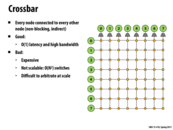

Question Could somebody explain how this picture shows that every node is connected to every other node? I see that there is a path from every node to every other node, but that is the case in the other topologies we looked at as well. From the picture it looks like a packet would have to travel through several switches to get to its destination, but I think in lecture Kayvon mentioned that the links could be thought of as instantaneous?
This comment was marked helpful 0 times.

@mschervi In my opinion, each node is directly connected to all switches in its row and its column.
This comment was marked helpful 0 times.

@Xiaowend, Based on your reasoning, would we expect n-1 wires from each node in the graph, with each wire going to a different switch? I am still confused about this as the slide is slightly confusing.
Also, can someone go over the difference between direct and indirect graphs in terms of this architecture setup.
This comment was marked helpful 0 times.
@akashr This network is indirect because all of the nodes sit on the "outside" of the the network. That means, to pass data between any two nodes, the data has to go between different switches, but never has to pass through another node. If a graph has a node on the actual path of data transmission, then it is a direct network.
This comment was marked helpful 0 times.

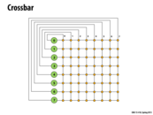
I think @Xiaowend's comment is correct. Every switch connects a directed pair of node (i,j). Since, there are N^2 possible pairs, hence we need N^2 switches. This must be true to ensure:
1. O(1) latency : If there weren't wires from node i to each switch in its row and column, then we would not get O(1) latency (1 hop to reach any other node j)
2. Non-Blocking: Because of N^2 switches with different wires, any 2 nodes, i and j, can communicate to each other irrespective of any other communication that might be occurring.
This comment was marked helpful 0 times.

Here @Xiaowend's comment is correct. It is just like a complete directed graph and you put a switch on each edge in the graph.
This comment was marked helpful 0 times.
Since everyone has a direct connection to every other node, we have a constant time latency to get a message from any node to another node.
This comment was marked helpful 0 times.
As a consequence of the constant-time access between every node, this design is more expensive than others and less scalable because it requires N^2 wires.
This comment was marked helpful 0 times.
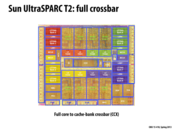

Note that the crossbar is about the size of a core, and that all of the caches lie between it and the the cache's core.
This comment was marked helpful 0 times.
Oracle reports the bandwidth of the crossbar tops to 180GB/s, while Core-i7's QPI is around 10-20 GB/s. It seems full crossbar does offer a incredible performance boost.
This comment was marked helpful 0 times.

Still, even with great performance gains, you loose a whole lot of the dye to just the interconnect.
This comment was marked helpful 0 times.
@ToBeContinued. You're comparing inter-chip communication via QPI to inter-core communication on the same chip via the T2 crossbar. That's not a fair comparison. A more fair comparison would be to compare the crossbar's bandwidth to the ring bus bandwidth on a modern Intel CPU.
This comment was marked helpful 0 times.
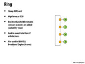

The ring approach connects each pair of vertices using $O(n)$ routing distance, so there is high latency. There are only a linear number of wires needed to connect each pair of nodes, so the ring is easily scalable. In modern processors, this ring approach is used, but there are multiple rings connecting a set of nodes. The rings may send the data in different directions (so node 0 might route to 1 in one of the rings, or 1 might route to 0 in another). This allows for easier scheduling, as the processor can choose to route a message to the left or to the right. Using multiple rings, the more connections also allows for higher bandwidth.
This comment was marked helpful 0 times.
There is a scalability issue because if we cut the network in half, we will always have only 2 links crossing the cut. Therefore this has low bisection bandwidth since.
This comment was marked helpful 0 times.
The ring is directed topology (because communication between 2 nodes might have other nodes in between) and is blocking (because paths may collide during simultaneous communication)
This comment was marked helpful 1 times.
Although it appears that the nodes are on the "outside", we must keep in mind that the switches have only one node connected to it. As a result, communication between two nodes might have switches (with one nodes) in between. This results in a directed topology.
This comment was marked helpful 0 times.
Note that this is different from the crossbar because each intersection is an actual node instead of the nodes sitting on the outside. (It is a direct network rather than an indirect one.)
This comment was marked helpful 0 times.
Here, we use fewer switches and have lower latency. But it is blocking and the switches in the middle can be busy and blocking when many nodes in left uppermost send packets to nodes in right undermost.
This comment was marked helpful 0 times.
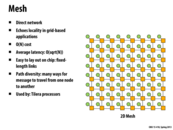
Average latency is O(sqrt N) because the width and height are both about sqrt N in terms of the number of nodes. In the worst case scenario, to get from node A to node B, we have to travel sqrt N nodes to the left or right to get to the correct column and sqrt N nodes to the top or bottom to get the correct row. 2*sqrt N = O(sqrt N)
This comment was marked helpful 4 times.
Here we can see that every node has a switch and a fixed number of links (or wires) connected to it, so it has a blocking topology.
This comment was marked helpful 0 times.
The bisection bandwidth of a mesh is O(sqrt(N)). Here's a simple way to think about it. In a square 2D mesh topology like the one above, there are N nodes, and any vertical line will bisect sqrt(N) links.
This comment was marked helpful 0 times.
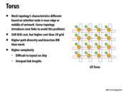

Here, it seems to be a combination of mesh and ring. It has higher path diversity but relatively more complexity to layout
This comment was marked helpful 0 times.

The asymptotic cost of this layout is the same as a mesh, but the latency is not so dependent on position, as if you're on one end of the grid, you can still get to the other end reasonably by using one of the rings.
This comment was marked helpful 0 times.

In 2D torus,each node is directly linked to its 4 nearest neighbors. The drawback is when the size increases, so dose the diameter of the network. Thus, it may be difficult to layout on chip when the size is big.
This comment was marked helpful 0 times.
@bottie: clarification. In a 2D torus, each node is directly linked to its 4 nearest neighbors. You mentioned it was sqrt(N). While in the above illustration 4 happens to be sqrt(N), that was just a coincidence for N=16. If I doubled the size of the network and maintained its torus topology, each node would remain connected to four others, even if N got arbitrarily large.
This comment was marked helpful 0 times.
In the 2D mesh, both average case and worst case performance is better for a node that is in the middle of the network. The Torus addresses this problem by connecting the edge nodes, making the position of the node irrelevant in terms of performance.
This comment was marked helpful 0 times.

From my understanding, this topology should be blocking as well since both ring and mesh are blocking.
This comment was marked helpful 0 times.

Interestingly, for applications with high spacial locality (such that communication is primarily between nearest-neighbor nodes) the effective average latency of communication should be O(1) instead of something like O(sqrt N) -- this would be a good choice for a machine dedicated to something like 2D finite element problem with periodic boundary conditions.
Sandia's Red Sky (built in 2009) used a 3D torus network topology for physics simulations. As far as I can tell it was decommissioned last year.
This comment was marked helpful 0 times.
Question Does higher bandwidth solve the bus contention problem? For example, what happens if nodes 0 and 7 and nodes 1 and 6, communicate small amounts of data at a very high rate? Here it seems having 2 separate low bandwidth links between the roots might avoid collisions.
This comment was marked helpful 0 times.

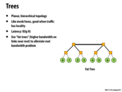
Good observation. The picture in the slide actually abstracts away implementation details. Fat trees typically employ a larger number of routers and links to implement the upper layers that appear to have "fatter" links in the picture. E.g. the the 8-node network in the slide could look something like this: http://www.design-reuse.com/news_img/20040402_brescia2.gif
On a side note: if you notice in the last picture all routers have 4 links, except for the ones in the top row, which only have 2. To build fat trees where all routers have the same radix (same number of links) the top row routers are often "folded". To get an idea of how this looks, go here http://users.ece.cmu.edu/~mpapamic/connect/ and select "Fat Tree" as the topology to see an example.
This comment was marked helpful 4 times.

Question: Is the cost in this case also O(lgN)?
This comment was marked helpful 0 times.
In this lecture, we've discussed cost in terms of the number of resources to build the network. Is this was not a "fat tree" and all links were one unit, then the cost of the network would be O(N).
If the width of a link is proportional to the number of subtree nodes it services, the cost would be O(NlgN). I'll let you puzzle over why.
This comment was marked helpful 1 times.

Because a tree with n vertices has (n-1) edges, the cost for all links being one unit is O(n). The second one, you can get from the recurrence C(n) = 2C(n/2) + O(n) because this is a balanced tree.
This comment was marked helpful 0 times.
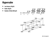
Radix: Every node has O(lg n) links coming out of it.
This comment was marked helpful 0 times.
Here, latency between two nodes is the number of different bits of binary representation of the two nodes, which is O(lg n).
And radix is number of bits of binary representation of a node.
This comment was marked helpful 0 times.

so for an n-dimensional hypercube it is just a projection of the hypercube into 3d space?
This comment was marked helpful 0 times.

Question: What will be the bisection bandwidth of this topology? My guess is O(N) since when the nodes are divided into two sets there are "parallel" links that connect pairs of node across each side.
This comment was marked helpful 0 times.
@yonguaw: Correct. Bisection bandwidth is N/2.
This comment was marked helpful 0 times.

Question: Is this a practical topology? It has a low latency, but there is also a large overhead of laying out the wires since it's difficult to project hypercubes into 3d space. In this example, which one would win?
This comment was marked helpful 0 times.
This topology appears to be directed since all switches essentially consist of one node.
This comment was marked helpful 0 times.
An advantage to this design is that you are directly connected to your N closest neighbors, but a disadvantage is that your machine needs $2^n$ processors to work in this configuration. Processors typically do have $2*n$ processors, so if you wanted to use this configuration, you might need more or less CPUs.
This comment was marked helpful 0 times.
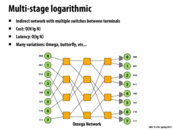

Question: Why is the cost O(N lg N) here?
This comment was marked helpful 0 times.
There are log(N) rows (stages according to wikipedia) and each row has N/2 nodes. So total cost is O(N lg N). In the picture, N=8, there are 3 rows and 4 nodes per row.
This comment was marked helpful 1 times.
Bisection bandwidth is O(N) as can be noted due to (in this case) n wires between switches.
This comment was marked helpful 0 times.

Many variations of multi-stage logarithmic networks, such as the Omega and butterfly networks, are isomorphic (topologically equivalent). These networks (delta networks), are "digit controlled" networks. In other words, the reason why there are $\log_2(n)$ rows (columns, in this picture) is because, starting from the left, each node is connected to exactly one 2x2 switch. Routing is entirely determined by the packet ("digit controlled"), which has $\log_2(n)$ bits. Each bit determines whether the packet is routed to the high connection or the low connection. Because each origin must be capable of reaching $n$ destinations, there must be exactly $\log_2(n)$ bits to account for the full $n$ outcomes.
This comment was marked helpful 0 times.
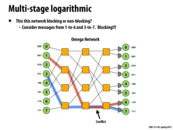
In general, a blocking network cannot guarantee that two messages with arbitrary source and destination can be sent simultaneously. The slide shows a case where two messages cannot be sent at the same time.
This comment was marked helpful 0 times.
All networks that we have considered except for crossbar are blocking.
This comment was marked helpful 0 times.
Direct means that nodes are actually within the structure, while indirect means that the nodes sit outside of the links.
This comment was marked helpful 0 times.
Here latency of mesh in worst case should also be O(sqrt(n)).
This comment was marked helpful 0 times.
Direct: Nodes are sitting on a switch in the network. Indirect: Nodes are not on the switches but instead on the edge of the graphs.
This comment was marked helpful 0 times.

Question: Should we also consider of bandwidth between nodes here? It is generally an important indicator when discussing about network.
This comment was marked helpful 0 times.

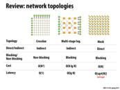
In addition: Ring, direct, blocking, O(n), O(n)
This comment was marked helpful 1 times.

@unihorn: I agree that bisection-bandwidth is also a very important metric.
Bisection-bandwidth:
1. Crossbar O(N)
2. Multi-stage: O(N)
3. Mesh: O(sqrt(n))
4. Ring: O(1)
This comment was marked helpful 2 times.

@chaominy In the answer the TA posted on pizza, the bisection-bandwidth of Mesh is O(N). Which should be correct?
This comment was marked helpful 0 times.
@TeBoring, chaominy: bisection bandwidth of a mesh is O(sqrtN). Think of the number of links cut by a vertical line through the network. If the mesh has N nodes, there are sqrt(N) horizontal links.
This comment was marked helpful 0 times.
Question: in computer networks, circuit switching guarantees the arriving order while packet switching does not, is it the same case here? Is there kind of virtual circuit approach applies here?
This comment was marked helpful 0 times.
@yingchai I think that it should still apply for the "network-on-chip" network. If you consider the case where a certain path has high contention and 1 packet is waiting for another packet to be sent due to buffering of packets, and another packet (with the same source and destination as the first) gets sent but the path for this packet has less contention. This second packet can definitely reach the destination before the first.
This comment was marked helpful 0 times.

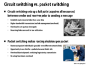
In circuit switching, sending a message requires establishing a connection to the destination, upon which to send the entire message in full; During this transaction, the resources that comprise the connection remain dedicated to it, meaning that no other data can use them and all pieces of data follow a fixed, unchanging path.
In circuit switching, quality and reliability are guaranteed: no pieces of data will fail to arrive, and no sharing of resources means that one can expect full bandwidth to be dedicated to the transaction. Also, since the path is predetermined beforehand, less transfer time is used than packet switching. However, this method does not use bandwidth efficiently, as no other transactions can use resources until the given one completes.
In packet switching, the data is broken up in the small parts which are sent, irrespective of one another, through the network; these packets independently seek out the shortest path on the fly as circuits become available. Once all packets have reached their destination, they are reassembled according to the original data order (each packet contains a header that denotes its original order and how many packets comprise the original data).
Packet switching makes the most efficient use of bandwidth: Unlike in circuit switching, where the path is laid out prior to data transfer, packets can set and revise the most efficient path as resources become available. In addition, sending data does not require waiting until a direct path is available. Packet switching also tends to scale better, as there is little overhead or unnecessary seizure of resources. However, packet loss can hinder efficiency, and reliable transfer requires more elaborate protocols than circuit switching.
This comment was marked helpful 1 times.
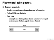
The error code is put at the end for convenience.
This comment was marked helpful 0 times.

The Error Code appended to the end of the payload is used as a check to ensure that the entire packet was transmitted properly. One example of a type of error code is a checksum, which is a function which takes in the payload data as an input and returns some bytes depending on the input. When the packet is received, the receiver can recompute the checksum from the payload and compare it to the errorcode that was received to see if any data could have been altered.
This comment was marked helpful 1 times.
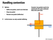
Dropping only one of the packets is important to a dropping message solution to handling contention. In this solution, a switch has two packets that both need to use the same outbound link, so the switch sends back a negative acknowledgement to one of the nodes that their message has not been sent. If the switch instead dropped both messages, both would continue to try resending, creating the same contention. The nodes continue doing work trying to send their messages, but no task is ever completed, creating an instance of live lock.
This comment was marked helpful 0 times.

In this slide, Kayvon mentions that the case where both packets are dropped could lead to deadlock or livelock. He called it a standard partial resource acquisition problem. I believe one solution to this general problem is always to access the shared resources in the same order, thus avoiding deadlock or livelock. Is it possible to apply that solution in this case? It seems like once two packets are entering the same node and we want to drop both, it's too late.
This comment was marked helpful 0 times.
@pd43 If by same order, you mean in a round robin style, that seems like a good solution. However, if you mean by giving priority to one link over another, it's possible that you may run into a starvation problem if packets keep coming in from the prioritized link and preventing the other links from sending their packets.
This comment was marked helpful 1 times.
Isn't it possible though to still reach a situation of starvation without prioritized links? For example, if node A is continually sending packets and node B continually gets rejected because A's packets always reach the switch first. What would be a solution to this situation? Or is it just unlikely enough that it doesn't need to be handled?
This comment was marked helpful 0 times.
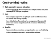

What the second bullet under costs is saying is that this method leads to many more idle links than packet-switching due to the high granularity. The path is reserved until the message reaches the destination. Even after then end of the message passes through a link at the beginning of the path (meaning that link will no longer be used by that message), that link cannot be utilized until the message actually reaches the destination. Any routing system that leaves too many links idle is not preferred.
This comment was marked helpful 1 times.
Another benefit to circuit-switched routing is that messages can send faster because they do not have to do checks in the middle of the data transmission to make sure there is no contention.
This comment was marked helpful 0 times.
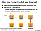
In lecture, this slide showed a single packet being sent from the source to the destination. The packet took 4 units of time to copy from one node to the next, with the link between the source and target node being marked as a "Busy Link" during the transfer. We complete the entire transmission in 12 time steps, 3 node transfers times 4 time steps per node transfer.
I suspect that this might give poor performance if the cost to travel through the links is different since links will sit idle with the packet unable to make progress if we are waiting on a long latency link.
This comment was marked helpful 0 times.
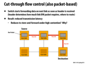
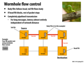
In lecture, this slide showed a single packet being sent from the source to the destination. While the time taken for each individual transfer is the same as the previous slide, once the header is sent to the next node, we can begin copying to the next node before the original transfer is even complete. For instance, the tail of the packet might be in the first node, the middle 50% of the packet in the second node, and the head of the packet in the third node.
While we use more links at a time than the previous slide, we complete the entire transmission in only 8 time steps since (in this example) we only need the first 50% of the packet before we can begin copying to the next node. Thus at time step 5, the first 25% of the packet is already at the destination.
In the high contention case, since we can't reserve future links, we will probably just devolve into the previous slide's Store-and-Forward model.
This comment was marked helpful 1 times.
Here the latency of store-and-forward is 4n, and the latency of cut-through-flow is ~2n where n is the number of links from source to the destination. If the data is m times bigger than the header, the latency of store-and-forward is O(mn) however the latency of cut-through-flow is O(n). Therefore the packet is larger, we saved more latency in cut-through-flow rather than store-and-forward.
This comment was marked helpful 0 times.

Question: From the lecture video, first two packets needed to be in a switch for the first switch to move to a next switch. For example, it went
4 - 0 - 0 - 0
3 - 1 - 0 - 0
2 - 2 - 0 - 0
1 - 2 - 1 - 0
but if the header packet reaches the second switch, why can't it jump right into the third switch, so it goes like
4 - 0 - 0 - 0
3 - 1 - 0 - 0
2 - 1 - 1 - 0
1 - 1 - 1 - 1
Is it due to the latency reserving the link so the header had to wait for 1 time step or because the header has size of 2 packets in this example? It seems like Wormhole flow control is doing it.
This comment was marked helpful 0 times.
@raphaelk In terms of terminology, the whole thing is just one packet broken up, not four packets. In this example, the wait is because the header has a size of two pieces (don't know if they would be flits since it's a continuous flow of data as opposed to breaking up the packets into specific pieces).
This comment was marked helpful 0 times.

Under high contention, the output link is frequently blocked, so the packet coming in is stored in a packet buffer until it can be sent out. Thus if the link is continually blocked, cut-through reduces to store-and-forward.
This comment was marked helpful 0 times.
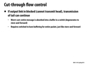
The hardware requirements for cut-through flow control are similar to store-and-forward because the network must be able to handle the worst cast where entire packets are being buffered at switches while the head is unable to make progress.
This comment was marked helpful 0 times.
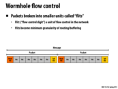

The overall idea of wormhole flow control is to have the packets "inch" between nodes like a worm would inch along a branch. Once the head of the "worm" moves, the rest of the "worm" will follow along the same path one flit at a time. This makes the request travel much faster through the nodes, and frees up any resources left after the tail of the worm has passed through.
This comment was marked helpful 0 times.

Because flits are much smaller than regular packets, it naturally follows that a network using wormhole flow control requires much less buffer space within its nodes than store-and-forward or cut-through based networks. This could lead to reduced hardware costs.
This comment was marked helpful 0 times.
Question What's the difference between using flits and decreasing packet size to the size of the flit? Is it because the body and tail flits don't have all the information to travel by themselves and can only follow the head flit? In that case, is the reason why flits are preferable because there's less total data to transfer? (Less space allocated for head/tails?)
This comment was marked helpful 0 times.
@Xelblade I think the difference between the 2 is a matter of abstraction vs implementation. You can think of packets as individual pieces of information a source node wants to send to a destination. How that data eventually reaches the destination (flits vs whole packets) doesn't really matter to the source as long as its message arrives and it doesn't really matter to the destination as long as the destination receives the entire packet.
The abstraction: sending individual piece of information from source to destination.
The implementation: flits.
This comment was marked helpful 1 times.

Of all the caterpillar pictures that could have been used, you ended up choosing one of the truly terrifying and rare carnivorous caterpillars. This comment isn't useful, but I thought I'd share.
This comment was marked helpful 0 times.

Here's how I remember packet-based routing. Imagine the packet as a tour group (and the people are the data). Store-and-forward is like moving from location A to location B on your tour, but you only move from location B to C once everyone in the tour group (packet) gets from A to B. Cut-through flow is similar, but instead of waiting for everyone to get from A to B, those who get to B are immediately funneled to C. Wormhole flow cuts the large tour group (packet) into mini-groups (flits) that are numbered. Each mini-group waits for everyone in their mini-group to arrive at location B and are then immediately taken to location C. More than one mini-group can be at a location, but no higher numbered group can be at a later location than any lower numbered group. Also, if group #1 (the head) stops, all the other groups can't move.
This comment was marked helpful 0 times.
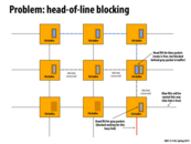
The blue flit in not allowed to make progress because the gray packet has already reserved the links. Since the head of the gray lint packets is stuck since the link is busy, the blue flit packets are stuck as well.
This comment was marked helpful 0 times.
Question: How is this different from Cut-through flow control algorithm if every packet buffer in switches had size of 1?
Are they basically similar thing except in different scale?
This comment was marked helpful 0 times.
I think it was briefly mentioned in class that the link between two nodes, where heads of two packets, being marked "reserved" could be little misleading because if the node where the head of gray pack is at had one more buffer, blue could use that idle link to make progress, while gray packets are holding their position (while head is being processed).
This comment was marked helpful 0 times.

@raphaelk I think the only real difference is what happens when the head/first packet blocks, in cut-through if the head is blocked then the tail and other body packets continue transferring while in wormholes if the head flit blocks the rest of the packet waits. In cases where there is no blocking I think your intuition on wormholes just being cut-through with smaller packets is right. I suppose the real thing to look at here is the difference between packets and flits.
The wikipedia article actually has an example (http://en.wikipedia.org/wiki/Wormhole_switching) and it even says "This, however, can be confusing since cut-through routing does the same thing" in reference to buffers and transmission, once again making me think the only difference is the sizes.
This comment was marked helpful 0 times.
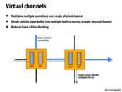
Instead of having one queue of size 2 (can only wait on the gray packet, can't even look at the blue packet), have multiples queues (in this case 2 queues of size 1) and look at both to see if either can make progress.
This comment was marked helpful 0 times.
In this case, progress for both flits can only be made if both move in different directions (as in the case above). Otherwise only one flit will make forward progress.
This comment was marked helpful 0 times.
Also, to add something mentioned by Hongyi during the final exam review session, having virtual channels doesn't allow you to send 2 different packets in different directions simultaneously. You can still only send one at a time but now you are not limited to serving all packets in the order they arrived in case a link is blocked.
This comment was marked helpful 0 times.
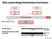
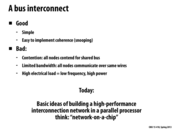
The problem with this system is contention, as there is sharing of the same resources. In this situation, it makes sense to have a more complicated interconnect system than just a shared bus.
This comment was marked helpful 0 times.