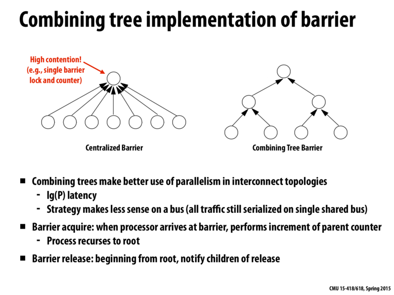
In left diagram, top circle is barrier and bottom circles are processors? If so what does circles in right diagram signifies. If possible, can someone please summarize the main idea of this slide.
jazzbass
@rbandlam In the left diagram, the top circle represents the lock that all of the threads are contending for to increment the barrier counter.
The idea of the right diagram is to have several small barriers. The threads are represented by the circles in the bottom of the tree. The parent nodes represent barriers. So, two threads will pass their parent barrier, then only one of the threads (could be any of them, let's use in this example the one with the smallest index) signals its next parent barrier, and so on until the final barrier is reached.
subliminal
Another tree-based barrier I found interesting was the static tree barrier, which has each thread assigned to a node in the tree. Each node sets a bit in its parent when all its own bits are set, recursing up to the root, and then spins on a local sense. The root sets the local sense when its bits are set.
aznshodan
what would be an example of combining tree barrier? Can anyone give me a code example of how this works?
sanchuah
I agree tree structure barrier can reduce contention of lock operation, but why can it decrease latency to O(logN)?
jazzbass
@sanchuah I believe that before all of the P threads were contending for the same lock, therefore we must do P work serially. Now we have several locks, so the barrier progress can be done 'in parallel' in log P steps.
lament
Could someone provide an example of hardware where a tree-based barrier implementation is useful? It says on the slide that it depends on the network topology, which makes sense - I'm curious about examples where such schemes are used.
In left diagram, top circle is barrier and bottom circles are processors? If so what does circles in right diagram signifies. If possible, can someone please summarize the main idea of this slide.
@rbandlam In the left diagram, the top circle represents the lock that all of the threads are contending for to increment the barrier counter.
The idea of the right diagram is to have several small barriers. The threads are represented by the circles in the bottom of the tree. The parent nodes represent barriers. So, two threads will pass their parent barrier, then only one of the threads (could be any of them, let's use in this example the one with the smallest index) signals its next parent barrier, and so on until the final barrier is reached.
Another tree-based barrier I found interesting was the static tree barrier, which has each thread assigned to a node in the tree. Each node sets a bit in its parent when all its own bits are set, recursing up to the root, and then spins on a local sense. The root sets the local sense when its bits are set.
what would be an example of combining tree barrier? Can anyone give me a code example of how this works?
I agree tree structure barrier can reduce contention of lock operation, but why can it decrease latency to O(logN)?
@sanchuah I believe that before all of the P threads were contending for the same lock, therefore we must do P work serially. Now we have several locks, so the barrier progress can be done 'in parallel' in log P steps.
Could someone provide an example of hardware where a tree-based barrier implementation is useful? It says on the slide that it depends on the network topology, which makes sense - I'm curious about examples where such schemes are used.