
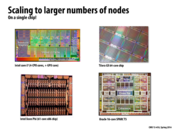

A note mentioned during the lecture. The i7 uses a ring interconnect, the xeon phi uses a collection of rings, the tilera uses a mesh interconnect, and the t5 uses a cross bar interconnect.
This comment was marked helpful 0 times.
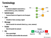

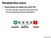
A packet is composed of many flits, flits do not contain additional headers. Two packets can follow different paths to their destinations. Flits are always ordered and follow the same path. This architecture allows for large packet size, small header overhead, and fine-grained resource allocation of the flits.
This comment was marked helpful 0 times.

What exactly are flits? Are they just bits in the packet?
This comment was marked helpful 0 times.

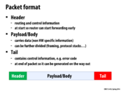
Large network packets are broken into smaller pieces called flits (not necessarily single bits). The first flit has information about the routing of the entire packet (destination). The data is sent through the body flits as a bunch of smaller chunks. Finally, the tail flit helps to close the connection between two nodes in the network.
Packets can follow different paths to get from one node to another, but if two flits belong to the same packet, then they must follow the same route between two nodes.
This comment was marked helpful 2 times.

A switch and a router aren't exactly the same thing. A switch connects units in a network, while routers connect different networks together.
As an analogy, the roads in a city are like switches in a network, while the highways connecting cities together are like the routers.
This comment was marked helpful 0 times.

If a flit contains multiple bits, why does the slide say it is a "flow control digit"? I was under the impression that if you break up a packet into a few pieces, each piece would contain more than a digit, but perhaps my understanding of the word "digit" in this case is incomplete...
This comment was marked helpful 0 times.

A flow control digit. It's like when a garden hose is spewing out water, and you stick your finger into it.
I'm pretty sure 'digit' isn't interpreted as a single number in this case. According to this, flits can range in size from 16-512 bits depending on the implementation.
Flits can in fact be further decomposed into 'phits' (physical transfer digits), which are even smaller (1-64 bits), defined as the unit of data transferred across a network channel per clock cycle.
This comment was marked helpful 1 times.
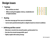

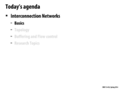
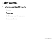
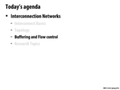
Topology can be thought of as a graph that represents the network.
Routing defines the path you're going to take if you want to send message from A to B in the graph.
This comment was marked helpful 0 times.
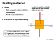
Just as a clarification buffering is defined by the first bullet point underneath it while flow control is defined by the second bullet point
This comment was marked helpful 0 times.
one disadvantage with static routing comparing to adaptive routing is fault tolerance. With a predetermined path, if anything between the start and end of the path is broken then the routing no longer workers.
This comment was marked helpful 0 times.

@ruoyul What you said applies more to internet routing, or in the interconnect network for multi-node supercomputer (like blacklight). On a processor, parts of the interconnect network breaking, would probably mean the chip is broken. Dynamic routing may still be valuable as it allows the routing of traffic around highly contended areas of the interconnect network. This would lower message latency.
This comment was marked helpful 0 times.

Dynamic routing is also important in the case where there is a link that is highly contended for, as in this slide.
This comment was marked helpful 0 times.
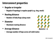

Just to clarify, the diameter is the maximum of the minimum distances between any two nodes. Based on what happens, it is possible that a longer path occurs, based on how the path routing is implemented and based on network business.
This comment was marked helpful 0 times.

How is a ring interconnect a regular graph? The degree of nodes on the edges/corners doesn't match the degree of nodes in the interior.
This comment was marked helpful 0 times.

@adsmith a ring does not have edges or corners--it's a ring! Every node has degree 2. It's A → B → C → A ...
This comment was marked helpful 0 times.
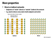

Is it possible to have a hybrid direct/indirect network? Ie, one where some endpoints are internal and others are external?
I suppose those are probably uncommon, practically speaking. Indirect networks have switches that do nothing but switch, while direct networks have switches that are tied to endpoints. Mixing and matching the two types might be more effort than using all of one or the otter type. But I'm completely making this up.
This comment was marked helpful 0 times.

http://web.mit.edu/6.173/www/currentsemester/handouts/L14-interconnect-1.pdf. Both direct and indirect networks have their advantages as well as their disadvantages. From my understanding, direct networks are good in that it is difficult to remove any node from the graph simply by breaking a connection, as there are many connections emanating from every node. In the event that the node itself fails, only one node is removed from the graph, and all other endpoints are still connected to the graph through another path. The disadvantage is that latency may not be quick for endpoints on opposite ends of the graph. Indirect networks are good in that they are better at relaying data, since the latency grows logarithmically rather than linearly for direct networks. However, having a node fail could remove many endpoints from the graph (single point of failure). Probably to have advantages of both and reduce disadvantages of either, one can create a hybrid network that is more efficient than either a fully direct or fully indirect graph.
This comment was marked helpful 0 times.

@tcz @pwei
I am not sure what you guys mean by hybrid networks, but if you are talking about adding an indirect network layer atop the direct network layer, I'd agree it would work well. However, I think the problem is a hardware/price situation, where redundancies are expensive. This paper shows that added routes to a direct network (Torus routing) can bring down network latency significantly http://ieeexplore.ieee.org/xpls/abs_all.jsp?arnumber=6182372&tag=1. Quite clearly this would be extremely expensive to implement (direct networks themselves are really only used in supercomputers and high end routers, apparently).
If you guys were talking about removing the directness from the network or adding routes the the indirect network proposed without achieving a full direct network, I think you'd only be creating a network specific to certain situations. It might seem reasonable to say you are simply taking the best of both worlds, but you are also eliminating some of the best of both of those types of networks: it being no longer direct and there being no longer a guaranteed logarithmic time connection.
This comment was marked helpful 0 times.
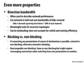

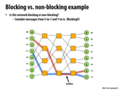
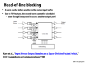
Question: The next slide supposedly shows an example of a blocking network. However, in the network shown, there does seem to be a path connecting any permutation of sources and destinations. Why, then, is it blocking? The reason given on the slide seems to have no relation to whether or connecting any permutation of sources and destinations is possible.
This comment was marked helpful 0 times.

As shown in the slide, you can't actually connect 1 and 6 simultaneously with 3 and 7 since they would be forced to share a line. Thus any permutation that paired 1 with 6 and 3 with 7 would have a conflict. The question of blocking and non-blocking is whether every permutation can communicate simultaneously, not just if they can be connected.
This comment was marked helpful 0 times.
To clarify, by a "connecting any permutation of sources and destinations", this slide means the network is able to support connecting every possible configuration that connects every source node to a destination node simultaneously.
This comment was marked helpful 0 times.

Is blocking/nonblocking a property of the topography, or the actual hardware? I.e. if the topography allows for 2 non conflicting paths, but static routing causes connections to conflict, is that considered as blocking or nonblocking?
This comment was marked helpful 0 times.

I think blocking/nonblocking is a property of topology at least in the context of this and the next slides. We can determine whether a design is blocking or not by just looking at the graph while routing is more an implementation level issue.
This comment was marked helpful 0 times.

Could someone explain how exactly we define "cutting the network in half" in bisection bandwidth? Is it any partition of the graph into two sets?
This comment was marked helpful 0 times.

I believe the partition has to be into two equal sets, and generally we care about the minimum such cut where we see the worst case bandwidth. The sets are equal because we want to maximize the amount of data that will have to pass through this cut (in this case we expect half) so that we can get a meaningful idea of worst case network capacity.
This comment was marked helpful 0 times.

I didn't really understand the term bisection bandwidth very well so i trying to find some good sources online. Here's one that i found helpful : "A bisection of a network is a partition into two equally-sized sets of nodes. The sum of the capacities of links between the two partitions is called the bandwidth of the bisection. The bisection bandwidth of a network is the minimum such bandwidth along all possible bisections. Therefore, bisection bandwidth can be thought of as a measure of worst-case network capacity"
And here is the article where i found it on; it discusses bisection bandwidth in detail and provides a great explanation using clear diagrams :
http://etherealmind.com/bisectional-bandwidth-l2mp-trill-bridges-design-value/
This comment was marked helpful 1 times.

Are blocking networks an issue with packet-switched networks? I feel like blocking networks are only an issue when the network is circuit switched. A blocking network would prevent some circuits from being made at some times, but in a packet-switched network, the blocked link would quickly become available as the link is only blocked for the duration of a single packet. Is this correct?
This comment was marked helpful 0 times.

That sounds correct to me. I think the issue is if you wanted to say establish a connection, you'd need control over the wire yourself. But if you're just sending packets, I think you're correct, you wouldn't have it for long.
Although, I think it's still an issue, since if all nodes on the left were sending data at a high frequency, the link with the conflict couldn't keep up, and would therefore decrease the overall throughput. Whereas if there weren't any conflicts, we could just have the maximum throughput of the links/switches.
This comment was marked helpful 0 times.

So the conflict only happens if the two messages want to go along the same connection? Does it matter if they want to go through the same switch? If going through the same switch does matter, then there are a lot of ways to block messages in this network, since pairs of nodes share a switch at the right-hand side.
Also, I'm somewhat confused about the difference between blocking and rearrangeable non-blocking. If going through the same switch doesn't matter, then wouldn't this be rearrangeable non-blocking? Because you can rearrange the connections on the inside of the network to make the 1-to-6 message go to the third node in the second column, then the third node in the third column, and then the last node in the third column.
Am I misunderstanding rearrangeable non-blocking, or is it the fact that they go through the same switch that causes the conflict?
This comment was marked helpful 0 times.

Rearrangeable non-blocking doesn't mean you can rearrange links, which is what I believe you're saying in your example. It means that you can connect any permutation of sources to destinations (3-to-7 and 1-to-6 is one permutation), but in order to switch to another permutation (e.g. also connecting 2-to-4) may require switching how you connected 3-to-7 and 1-to-6. A strictly non-blocking network means that no matter what permutation of sources and destinations you have, or how you switch between permutations, you won't have to rearrange the connections.
This comment was marked helpful 0 times.
@tomshen The confusion might be over the term "connection". I understand it to mean a path along the network from a source to a destination, but jmnash may have misunderstood the concept to the edge from one node on the network to anotter.
@jmnash The blocking does not happen at the switches, but at the edges/wires/connections.
This comment was marked helpful 0 times.
What does the word 'blocking' actually refer to? Does these has anything to do with blocking and non-blocking send? The word blocking comes from the fact that if we want to send from 1->6 and 3->7 at the same time, one of them will block the other, right?
This comment was marked helpful 0 times.

@rouyul I believe "blocking" refers to one message preventing the other from moving forward, as you said. This occurs because both 1->6 and 3->7 want to go through the same switch and connection. I think this isn't related to blocking and non-blocking send, except that in both scenarios one message/send is preventing another from making progress. Can someone verify this?
This comment was marked helpful 0 times.
In general, "event a is blocking" means that there exists some situation where the occurrence of event a prevents some other even from occurring.
Blocking/non-blocking send has to do with program execution. A blocking send will halt other execution until the send completes. A non-blocking send will allow other code to execute.
In this case, @aew is correct. A message from 1->6 blocks the event 3->7 from happening.
However, I'm not sure that switches have anything to do with blocking/non-blocking. I think it all comes down to wires, because wires can only carry one message at a time, whereas switches can handle multiple messages in some way.
This comment was marked helpful 0 times.

Still not sure what rearrangeable non-blocking means. Can anyone clarify this concept?
This comment was marked helpful 0 times.

How do cache protocols change with different topologies? It doesn't seem like a broadcast protocol would be efficient in something like a Tree topology. In fact it doesn't seem like a broadcast protocol would be efficient in anything but a Bus or Ring topology. Would other interconnect topologies use primarily directory based cache protocols?
This comment was marked helpful 0 times.

@tchitten. Just to be clear, make sure the coherence protocol (MSI, MESI, etc.) is separated from the details of the implementation of the protocol (forms of snooping, directory based, etc.)
This comment was marked helpful 0 times.
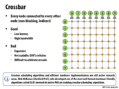

Is the image not supposed to be a grid, but rather the connection between for example 0 on the left and 3 on right goes 'under' the nodes below 0 through 2 and is only actually connected at the node under 3?
This comment was marked helpful 0 times.
In my understanding, no. It would still have to go through the switches along the way. Though I suppose you could implement it that way, there would just be a ton more links in the network.
This comment was marked helpful 0 times.
I agree with @cwswanso. If 0 on the left had a separate wire going to every endpoint on the top, sure there would be a great deal of speed up, because there is a dedicated link between endpoints, but there would also be a huge problem for scalability. Then, adding another node on the top would require that each node on the left be capable of having another wire attached to it. This could also get confusing as an endpoint could start receiving information on multiple lines.
This comment was marked helpful 0 times.

With a separate wire from every node to every other node, there would still only be N^2 wires, which doesn't seem worse than N^2 switches (shouldn't a wire be simpler than a switch?).
I'm curious to know, though: does a wire necessarily consume power all the time the chip is running, or only when data is being sent through it? If the latter is the case, would it be right to say that whenever a crossbar topology can be used feasibly, it is always desirable to do so (barring cost?)
This comment was marked helpful 0 times.

I think there are physical limitations on the number of wires you can have emanating from a single node. Having N wires attached to a single node doesn't sound scalable at all.
This comment was marked helpful 0 times.

So for this case any combination of nodes connecting together does not really influence other combination from communicating with each other. Since it is unlikely that there is a case where all nodes need to reach all others, it seems that blocking/non-blocking issue may not be too much of the importance when network is well structured?
This comment was marked helpful 0 times.
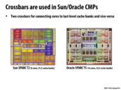

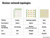
The crossbars shown in the chips above ("CCX" on the left, "Cross Bar" on the right) illustrate one of their biggest disadvantages: they don't scale well. In both chips, the amount of die space taken up by the crossbar is on the order of an entire processing core. One of the main advantages of this construction (as mentioned on the previous slide) is low latency; every node is directly connected to every other node.
This comment was marked helpful 0 times.
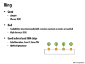

The reason why Intel is using ring is that the number of cores in modern CPU has not been high enough to make the low cost unattractive. There is also optimization to reduce latency, such as connecting in two place on the ring (see Implementing Synchronization, slide 2). This connection allows each node to choose the shorter "arc" or the direction with smaller number of hops.
This comment was marked helpful 0 times.
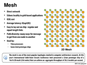

here the height of the mesh and the width of the mesh is sqrt(N). Hence to get from one end of the mesh to the other in the worst case we would have to travel sqrt(n) to reach that nodes row and then another sqrt(n) to reach that nodes column. Hence a total latency of 2*sqrt(n) => O(sqrt(N)).
This comment was marked helpful 2 times.

Question:
If the O(sqrt(N)) latency means the travel cost for one node to another, what does the O(N) cost mean?
This comment was marked helpful 0 times.
The $O(N)$ is the cost of the network. It is the number of nodes in the network. Here there is $1$ node for each processor connected to the interconnect. This gives us $O(N^2)$ nodes.
This comment was marked helpful 0 times.
For a network with N nodes, there are O(N) wires, so cost is O(N). Worse cast latency is 2 * sqrt(N).
This comment was marked helpful 0 times.
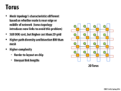

Graphically this looks the same as a mesh. How is it really different? Is it just that the nodes on the edge of the network have extra connections?
This comment was marked helpful 0 times.

Yes, I believe that's the case -- it's basically a mesh but with extra "wrap-around" links from the node on the end of a row/column to the node at the other end of that row/column.
This comment was marked helpful 0 times.

One important thing to note is the last bullet - unequal link lengths. For certain arrangements, it may be possible that the wraparound links are similar in length to the other links, but in most cases, these links have to traverse much more space. The chips we use typically (exception noted a few slides ahead I believe) are 2D-ish, so these wraparound links are not as simple as shown on the slide.
This comment was marked helpful 0 times.

Wraparound links are one way in which engineering complexity can be traded off for better performance (i.e., smaller average hop distance).
There have been proposals for more complicated networks based on the torus. One example is the iBT network (research paper, picture). iBT adds more links to the torus, further shortening diameter and average hop distance. On the other hand, it is almost certainly more costly to build in practice.
This comment was marked helpful 0 times.
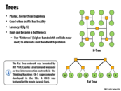
To quickly recap the point of a fat tree: For a normal tree, the H-Tree for example, there is bottleneck (a low bisection bandwidth) through the center node. Basically, if you cut the tree in half, there is only one link between the two halves. To make patch this up and make trees more realistic an option, the fat tree has thicker lines between higher links in tree, representing higher bandwidth. Thus, cutting the Fat Tree in half, will still result in only having one line between the two halves, but that one line will have a higher bandwidth.
This comment was marked helpful 0 times.
Note that the implementation of the fat link between the two roots can vary. For example, the fat link can be implemented by having another set of routers on top of the roots shown here that link to them, and having links from the roots to them to provide higher bandwidth (I believe this was shown in class?). I would also think that indeed having a link with more bandwidth as the picture suggests would be a valid implementation as well.
This comment was marked helpful 0 times.
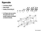

One thing that I think could be interesting from this is that adding an edge from any core to the bitwise negation of its representation would only require another link for every two cores, but should decrease the diameter by half.
If it were 6-dimensional, then the original diameter would be 6, but by adding this link, we would be able to get from 000000 to any node in at most 3 hops, as if a node has at most 3 1's in its representation, we can go directly, and if it has more, we can jump to 111111 and make it to the core in at most 2 hops.
The only issue I can see with this is some of the links are likely to be notably longer than others, but with the hypercube implementation for higher dimensions, we might already have this issue to some degree.
This comment was marked helpful 1 times.

The hypercube design seems really cool in theory, but I think they mentioned in class that very few computers actually use this format. What you said about nonuniform link lengths is probably a drawback; I can think of a couple others:
For higher dimensions, each router has a high number of wires going into it, which might increase routing complexity.
For anything higher than 3-D, projecting this design onto a 2-D circuit in a space-efficient way is probably extremely hard.
This comment was marked helpful 0 times.

What are properties of hypercube? Direct/indirect? blocking/non-blocking? What is the cost? What does it mean radix and number of links?
This comment was marked helpful 0 times.

Let's see if I can take a stab at these:
I think it's direct, as there weren't separate router nodes and non-router nodes drawn.
It's blocking, as you can't get from 0,0 to 1,1 and 0,1 to 1,0 simultaneously on the 2D hypercube.
Cost is the number of links, O(n log n)
Radix is the number of links out of each node, which is O(log n) since each of the log n bits of an n-bit binary number node can be flipped to give you a neighbor of that node.
This comment was marked helpful 0 times.
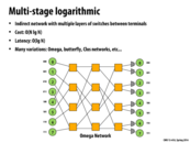

Multi-stage logarithmic networks can either be blocking or non-blocking, depending on the configuration of the wires and switches. This particular one is blocking as mentioned in a previous slide.
This comment was marked helpful 0 times.

Question: How exactly do we get O(1) latency in the crossbar topology? To go from one corner to another, don't we need to get through 2N switches?
This comment was marked helpful 0 times.

@rokhinip. With Crossbar, every node has a direct path to other nodes without getting through switches like Mesh, so the latency is almost O(1). And that's why it has a higher cost than other topologies.
This comment was marked helpful 0 times.

O(sqrt(N)) is an average latency
This comment was marked helpful 0 times.
@chaihf, the comments on the slide for graph seem to suggest otherwise. But I agree with you for we won't get O(1) latency.
This comment was marked helpful 0 times.
@chaihf, why is the latency almost O(1)?
This comment was marked helpful 0 times.
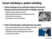
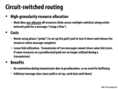
Additionally, circuit switching is more robust/reliable than packet switching, since you have a circuit dedicated to the session (for transmitting the data). With packet switching, you need to have mechanisms to check that all the packets are received successfully (no lost/malformed packets).
That being said, packet switching has quickly become much more common in today's communication networks, since it allows for different messages to make progress over the network (better provisions for fairness).
This comment was marked helpful 1 times.

The cons I see with circuit switching is that the overhead for setting up/tearing down the route can be high, and it results in low utilization because only one connection exists per route. The con with packet switching is there has to be a defined protocol for maintaining the integrity of packets. The logic for dynamically switching links during transmission can also be complex.
This comment was marked helpful 0 times.
Question: How is circuit-switched routing actually implemented? It seems really hard to have probing happen both in parallel and concurrently with other packets coming through the network. Do you associate a lock with each node in the network and just try to take locks along the path? This seems like it would be wrought with inefficiency.
This comment was marked helpful 0 times.

@wcrichto I'm not sure what you mean by packets coming through the network conflicting with probing because if its a circuit switched network all packets must have their paths setup up by some controller and so there should not be any free flowing packets or messages.
This comment was marked helpful 0 times.
@dtaveras: he's talking about the "probing" which, I'm assuming, is essentially done with a packet. You send a packet down to "scout" a path out, but there might be other "probes" that are scouting paths too, and it seems like there could be a lot of possible problems with contention for path building. That's what the slide seems to imply, anyway. If there was a central controller that has a personal "map" or something like that keeping track of all the routes, then it looks like we'd avoid any possible race conditions or deadlock, but you also just introduced a single point of failure in your system which may be bad for other reasons.
This comment was marked helpful 0 times.
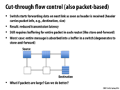
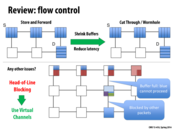
According to the TAs at the review session, while we have buffered transmission of a packet in cut through flow control, we still lock all the nodes on the path of the packet from the source to the destination. Therefore, we cannot have interleaving of flits from different packets. A disadvantage as a result of this is that we could possibly have some links in the route idle even though there might be a packet waiting to be sent using the idle link.
This comment was marked helpful 0 times.
I think here the cut-through flow control implies packet level flow control where the packet will be forwarded as soon as outport is free, but if the outport is not free then the whole packet has to be stored (absorbed). That's the reason for the buffer has to stay large which is similar to store-and-forward flow control.
This comment was marked helpful 0 times.
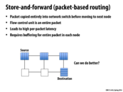
So if both store-and-foward and cut-through flow control buffers the entire packet in each router, is the only difference in how soon the data is forward? i.e store-and-foward send only when the entire packet arrives while cut-through start sending as soon as header arrives?
This comment was marked helpful 0 times.
Question: Why would cut-through flow control be setup such that all nodes on the path of the packet from source to destination are locked? I suppose this would prevent head-of-line blocking, but it seems that the penalty on throughput in this scheme would greatly outweigh those benefits.
@ruoyul: Pretty much. One key consequence is that because cut-through flow control begins forwarding as soon as the header arrives, the validity of the packet being forwarded is not checked until the very end, whereas in store-and-forward, the validity of the packet is checked at each node.
This comment was marked helpful 0 times.
@ruoyul I think the idea is that because cut-through flow control can start forwarding as soon as it gets data, it probably won't have to buffer the whole packet at each node. The buffers have to be allocated for the worst case, but that's not what usually happens.
This comment was marked helpful 0 times.
@spilledmilk, if it wasn't locked, then it's possible you would not be able to complete sending the data if the buffer isn't large enough. Imagine that you have a buffer of size of 1024 bytes and packets A and B, although the packets in this particular case are only 768~ each. The buffer fills up with packet A, then says oh I have space in my buffer let me transfer packet B. But for whatever reason packet A is blocked from going to the next node, so the buffer doesn't empty, and we only can transfer up to half of packet B. Information is going to get dropped (corrupted packet) OR we have to store a lot more metadata (recreate header for the remaining data of packet B) OR have a lot more communication regarding packet size and size of buffer etc etc.
It is a lot simpler to simply lock the path. With buffer sizes as large as the maximum packet size you do not need to worry about these edge cases and the overhead associated with solving them.
This comment was marked helpful 0 times.

QuickPath Interconnect (connecting Intel Core i7-family chips) uses 80-bit flits, with the first 8 bits for the header, the last 8 bits for error detection, and the middle 64 bits for the payload. src
This comment was marked helpful 1 times.

It seems to me that the wormhole flow control mimics the cut-through flow control in that data is sent in segments (with Wormhole we have flits, but with cut-through, data is forwarded once header information is known). I just wanted to understand why buffer sizes are smaller for wormhole. Couldn't wormflow degenerate to store-and-forward as well if there's a head of line blocking situation?
This comment was marked helpful 0 times.
@devs, I believe that it could degenerate to a store-and-forward if there is a head of line blocking situation.
It seems like the main difference between wormhole and cut-through flow control is the granularity of the data being sent. In cut-through, we sent over the entire data packet but here, we are sending over smaller segments/flits.
This comment was marked helpful 1 times.
@devs @rokhinip It looks like the granularity is indeed the main difference. From wikipedia (http://en.wikipedia.org/wiki/Wormhole_switching),
"Cut-through switching commonly called "Virtual Cut-through," operates in a similar manner, the major difference being that cut-through flow control allocates buffers and channel bandwidth on a packet level, while wormhole flow control does this on the flit level."
This comment was marked helpful 1 times.
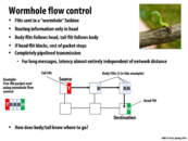
Can someone explains how does body/tail know where to go?
This comment was marked helpful 0 times.
@analysiser: My guess is that each flit has some kind of tag that associates it with a certain header, and each node stores the destinations of the headers that have passed through until the tail of that packet passes through.
This comment was marked helpful 0 times.
@devs: the buffers can be smaller because the flits can be broken up across multiple routers. In cut-and-forward, the entire packet was sent at once in a streaming fashion, so it was impossible to stall the send while the packet was half in one router and half in another. As such, our worst-case buffer size if the head got stuck was always the maximum packet size. In this model though, we could get away with only enough buffering on each router for a single flit (although we might get latency issues from doing that). The key difference that makes this possible is (as @spilledmilk was saying) that each flit contains a small header, so it can be handled without knowledge of the rest of the packet.
This comment was marked helpful 1 times.
Incidentally, I feel like a better name for this would be inchworm flow control. Thoughts?
This comment was marked helpful 2 times.
@analysiser: Not sure about this, but I think that it might work where each switch, once it sends the head to some other switch, won't send that switch flits from any other packet until the first packet's body and tail flits have all been sent. That way, the body flits don't need to contain any routing information; only the head and tail do.
This comment was marked helpful 0 times.
@mchoquet: Agreed. "Wormhole" sounds more like teleportation than anything else, while "inchworm" goes well with flits moving independently along the same path (the worm contracting and expanding as it moves) but always staying in order and not passing the head (since that would break the worm...)
This comment was marked helpful 1 times.
mchoquet - I think you mean "INCHidentally, a better name for this would be inchworm flow control."
This comment was marked helpful 1 times.
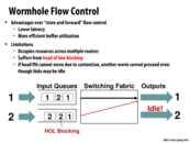


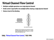
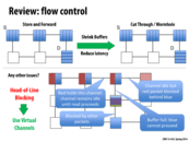
"Virtual Channel Flow Control" is actually a fairly simple concept, of splitting up different packets by their output destination.
As a metaphor, think about airports. At terminals, there are separate lines to board each plane. This is an example of "virtual channel flow control" -- the passengers are organized by their destination. Imagine if there was a SINGLE line at the airport to board all the planes, and no one could change order in line. That would drastically reduce efficiency!
This comment was marked helpful 3 times.
I like @smklein's example. Another metaphor for virtual channel flow control is the turn-specific lane on roads. Lanes are sometimes designated as "turn-only" to avoid the bottleneck that would result from putting all vehicles in the same lane. This way, vehicles that are turning can avoid waiting for cars that are going straight and vice versa.
This comment was marked helpful 2 times.
Without turn-only lanes, you get things like the Pittsburgh left.
This comment was marked helpful 1 times.
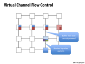

Here if we had a buffer per possible output, then wouldn't the blue flit that is currently blocked by the green flit be able to proceed, thereby allowing more blue to flow through?
This comment was marked helpful 0 times.

But here we only have two buffers/ lanes per router, and there are three types of packets (purple, blue, and green) at the router you're talking about.
This comment was marked helpful 0 times.

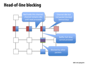
I think also that virtual channel flow would not be able to have a buffer at each router for every possible output because that would require predicting the maximum number of packets that would be buffered at a router at any one time (and it might also have high space utilization, e.g. use up a fair amount of memory, while not even using all of the buffers available at router at a time; or alternatively, if the buffers are split as on the previous slide, the buffer sizes might be too small). The idea behind virtual channel flow is to attempt reduce the amount of head of line blocking, but as depicted in this diagram, it cannot completely eliminate it.
This comment was marked helpful 0 times.
I think sss was referring to a buffer per possible output as in output link from the switch, not a buffer per possible destination. This would only require a number of buffer channels equal to the radix of the switch, which is a fixed constant.
This could still cause blocking (say if a very large packet was filling up the buffer and making a smaller packet going along the same output link wait), but I'm not sure if this would be considered HOL blocking per se.
This comment was marked helpful 0 times.
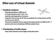

One related topic with virtual channels is in cache coherence, such as lecture 16, slide 31. Even though it may not be exactly the same, but the idea is similar. To avoid deadlock, and could also give priority to response virtual channels.
This comment was marked helpful 1 times.
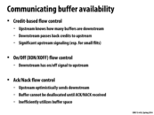
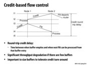
Throughput is better on a large buffer size because the switch is able to clear its buffer while waiting for a response to a credit update (a new flit to arrive).
This comment was marked helpful 0 times.
Elaboration on point 2: if there are few/small buffers, when sending a credit back to tell the source node to send more data, the buffers may drain, leaving the path idle and thereby degrading throughput. If there are many large buffers, the delay while waiting for the source node to receive the credit and send more data is not a problem since the big buffer at the switch that sends the credit is still being drained.
This comment was marked helpful 0 times.
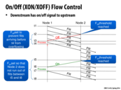

Seems that in order to send the ON/OFF at the right time, the downstream needs to predict the conditions of the network because it needs to know exactly how long the signals will get to upstream. How is this practical?
This comment was marked helpful 0 times.
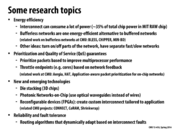

I found this link helpful since it covers many of the topologies discussed in lecture. In addition, this textbook entry covers routing techniques (both deterministic and adaptive), which describes some of the issues not covered in class as listed in the final bullet point.
This comment was marked helpful 0 times.
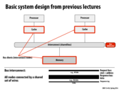
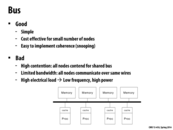
The shared bus would make contention a problem for the system
This comment was marked helpful 0 times.