


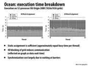

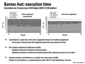
The black bar in the graph means the time waiting for the data that comes from other threads. The 4D blocking of grid reduces communication since it has less elements on the border than 2D block pattern.
This comment was marked helpful 0 times.

By plotting these graphs, we are able to see how to best optimize our code next. The crosshatched bars are all horizontally level in both graphs, meaning our workload assignments are sufficient. However, we see the communication bars are significantly higher in the graph on the right compared to the left, so we could try to capture more locality.
This comment was marked helpful 1 times.

SGI Origin 2000 is a family of mid-range and high-end servers manufactured by SGI. The largest installation was ASCI (Accelerated Strategic Computing Initiative) Blue Mountain at Los Alamos National Labs, with 48 Origin 2000 series 128-CPU systems all connected via HIPPI for a total of 6144 processors. See more here.
This comment was marked helpful 0 times.

4D layout is different from 4D assignment.
4D layout is about the layout of data (to decrease artificial communication in cache)
4D assignment is about work assignment among threads (to decrease inherent communication among neighboring threads)
This comment was marked helpful 0 times.
I have a guess for why synchronization on the right is longer.
First, 2D block assignment actually doesn't allocate same amount of work to each thread. (this can be seen from the bottom bar)
Second, due to unbalance of work, barriers need more time (to wait for the last). Thus, synchronization is longer.
One more interesting thing I found is, even though work is unbalanced in 2D assignment, the finish time still the same. I guess this is because there is barrier there.
Correct me if I am wrong
This comment was marked helpful 0 times.

@TeBoring: Yes, I think it's safe to assume that this example is running over many solver iterations (and perhaps also over many time steps), and there's a barrier at the end of each phase. That's why the total height of the bars is the same. Any imbalance in communication costs or processing gets added to the data wait or sync wait bars so the total is always the same.
It think that increases sync time in the 2D is actually due to the imbalance in both compute (busy) and also communication costs. Does how there's even more variation in the black bars than the hatched bars. Both of these effects could increase the time waiting to sync all the threads up at barriers.
This comment was marked helpful 0 times.
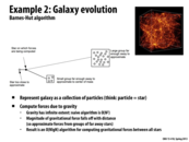

Quick review for high school physics. According to Newton's law of universal gravitation. The force caused by other star is ${GMm\over r^2}$, and the gravity is $g = {GM\over r^2}$ $G$ is constant, $m$ is the mass of star itself, $M$ is the mass of the other star, and $r$ is the distance between stars.
If $r$ is large enough, the contribution to total force can be really small. Thus, we can approximate it by grouping its neighbors.
For detail, see the wiki page
This comment was marked helpful 0 times.
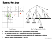

In Barnes-Hut, we divide the space into four quadrants. As long as there are a sufficient number o stars in a quadrant, we sub-divide that quadrant into four more quadrants.
To estimate forces on the red particle by all particles in the green box, if L is sufficiently small compared to D ($L/D$), we combine the forces of all particles in the green box and use this combined body to calculate gravitational pull on the red particle.
This comment was marked helpful 1 times.
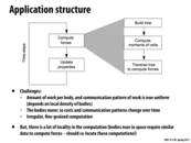

When we are trying to parallelize a program, such as this, it would be a good idea to see if the part of the program we are looking is in fact expensive. In this example, compute forces takes up the longest time and traverse tree to compute forces is sufficiently complicated enough for us to consider how to parallelize it.
This comment was marked helpful 0 times.

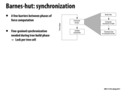
Speedup of certain parts of the program may also lead to slow down in other parts. As an example, in the following analysis of this use-case, we are assuming that we have a nice spacial tree which we an traverse. This allows the third component to be nicely divided for a parallel implementation. However, this tree does not come for free, as it increases the time to build it. On the other hand, if we are lazy and create a fairly unbalanced tree, this will make the third stage slower, at the cost of faster tree building. Of course, in our use-case it is likely that the speedup we get from a nicely balanced tree is larger than the time we can save from building it, hence we opted for this solution. Therefore, when designing these complex algorithms, it is important to look at each section of the workload, and decide if spending more time on some sections is worth the speedup in others.
This comment was marked helpful 1 times.


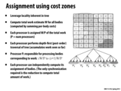
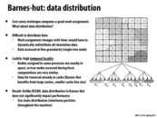
The work distribution here is irregular and changing all the time. So it is hard to come up with a good static assignment. However, the distribution is predictable because the distribution evolves slowly. So we can use the work amount of a body in the last timestamp to predict the work in the current timestamp. That's why we can use semi-static assignment in this problem.
This comment was marked helpful 0 times.
Question Why we don't use post-order traversal if we want to accumulate children's mass? I think we would like to use order {left,right,root} so we can add mass at the root phase?
This comment was marked helpful 0 times.
@DanceWithDragon. Good catch. The slide was edited to say depth-first (post-order) traversal.
This comment was marked helpful 0 times.

It was mentioned that we would want a large cache with small lines to store the data based on the tree structure here. Could someone clarify why that would be ideal?
This comment was marked helpful 0 times.

On some level this is true of most pointer-based data structures, that you want many cache lines, each about the size of one node. If you use a similarly-sized cache with large cache lines, you end up evicting a lot when you dereference a pointer to load a new node, and you get a fair bit of extraneous stuff. The computation has high spacial locality, but the data structure does not. The nodes are small, so if you have many small cache lines you can get a large portion of the tree into small cache lines and generate lots of hits.
There is likely something deeper here that I'm missing, though.
This comment was marked helpful 0 times.
I want to add some points to @jedavis's answer.
A large cache with small lines means a large work set, which can store the entire processing path. In this way, we can make sure that all the data traversed can be stored in the cache without evicting.
Another benefit is that with small lines, we can reduce artificial communication. The tree nodes are typical small and can't fill a large cache line. So if the cache lines are large, we would waste our time transferring useless data. The ideal situation is that the size of a cache line is equal to the size of the tree node.
This comment was marked helpful 0 times.

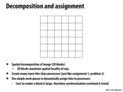
One interesting thing to note in this example is that the cost-zones assignment version has increased the work done by each thread, but the total time taken for each thread to complete decreases. The time spent reading data has gone down more than the time spent processing has gone up, resulting in a net decrease. Ultimately, if our machine only has this one task to work on, this is desirable, though if the machine were expected to multi-task, it might not be, as we could prefer that our processors be free to execute other tasks.
This comment was marked helpful 1 times.

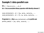
Assuming you have an infinite number of processors, to compute the scan of this array:
Every processor in parallel adds two nodes. The first two elements are now complete.
The first four elements are now complete.
The first eight elements are now complete
etc.
If we have p processors instead of an infinite number, we divide the work w as:
$w / p$
$w = O(N \lg N)$
So we have each processor computing $(N/p) \lg N$
This comment was marked helpful 0 times.

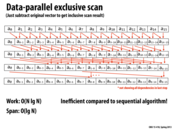
$O(n)$ work above the line (up-sweep) since it's $\sum_{i=1}^{\lg(n)-1}{\frac{1}{2^i}}$ sums, which is less than $n$.
$O(n)$ work below the line (down-sweep) since it's $\sum_{i=1}^{\lg(n)-1}{\frac{1}{2^i}}$ sums (in reverse order) in addition to the same amount of copies, which is less than $2n$.
Total work is this $O(n)$, about $3n$. Total span is still $O(\lg n)$, about $2\lg n$.
This comment was marked helpful 0 times.

Another way to understand this slide is to realize that everything but the first and last line is recursively computing scan on the odd-indexed elements.
(actually, that's not quite true. But it's quite close, and you can easily implement it that way)
This comment was marked helpful 0 times.

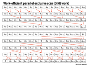
The flow seems to be chaotic at the first glance, but it is not hard to understand it thoroughly.
Imagine an inclusive scan is done in this way. First, it sums all the value in the same way as the first part. Then, it propagates the sum value down in the opposite direction of the first part, and ensures members in each step all have the correct value. ($a_{0-15}$)->($a_{0-7}$, $a_{8-15}$)->($a_{0-3}$, $a_{4-7}$, $a_{8-11}$, $a_{12-15}$)... In the process, it utilizes generated result efficiently.
When it comes to exclusive scan, the easiest way to do this is to move all elements one slot right. But it is unnecessary to waste time to do the extra work because we can break it down and insert into the later part. It maintains a law in each step: for the last $k$th step, the members in the position of $2^k$ multiply have been placed in the relatively correct way. So when it comes to the end, it completes the exclusive scan process.
This comment was marked helpful 0 times.


In up-sweep function, workload is N, span is lg N. In Down-sweep function, workload is 2N, span is lg N. So the constant here is 3 and 2. In fact, we really care about the constant. And the constant before N in workload can be improved to 1.5 in slides 23
This comment was marked helpful 0 times.
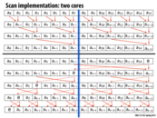

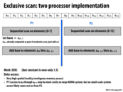
This slide serves as a reminder that the actual hardware we will be using for the implementation is important. The previous algorithms for scan were optimized for either one core, or an infinite number of cores. However, in reality almost all systems we use will be neither of these. We thus have to consider the best implementation for the specific systems we will be using (in this case two cores). In this case, the added work for the infinite core algorithm just isn't worth it given only two cores.
This comment was marked helpful 0 times.
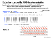
This is more efficient than the work-efficient formulation since we actually have at least as many "processors" as elements in the array so we can achieve the ideal $\lg n$ total time, but the work-efficient formulation doubles span.
This comment was marked helpful 0 times.
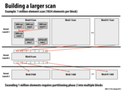

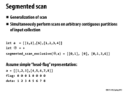


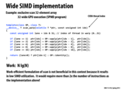
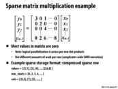
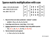
This code suffers from poor locality and the performance can be improved using a segmented scan. In a segmented scan, we break up the input array into small contiguous blocks and perform a scan of each of them. Though it performs more work, it can lead to better performance due to better utilization of the cache.
This comment was marked helpful 0 times.

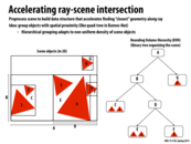
There is no proven best way to build the tree around the objects in the scene. What's often done in practice is to use the "surface area heuristic" as a guide to partitioning each level.
This comment was marked helpful 0 times.
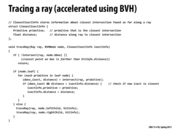
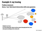
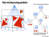
traceRay is a recursive function that computes the closest intersection of the ray ray with the scene geometry contained within the sub-tree rooted by node. As the ray is traced through the subtree, the struct isect maintains information about the closest intersection found so far. This information consists of the distance along the ray to the closest intersection, and a reference to the scene primitive that yielded this intersection.
traceRay works as follows:
It first determines if the ray intersects the bounding box of
node. If it does not intersect the bounding box, or if an intersection does exist, but is strictly farther than an intersection found so far, then he function returns. This "early out" is valid because it is not possible for any geometry insidenodeto generate a closer intersection.If the node is an interior node,
traceRaythen recurses on the nodes for the two children.If the node is a leaf node,
traceRaychecks for intersections between the ray and each primitive in the leaf (see call tointersect()function). If an intersection exists and that intersection is the closest scene intersection found so far, this information is stored inisect.
To give you a sense of how traceRay is used to make a picture, the overall basic structure of a ray tracer is given below. Notice how iterations of the outermost loop are independent and can be performed in parallel.
BVHNode root;

for each pixel p in image:  // iterations of this loop are independent
   Ray r = createRay(p)     // r is a ray traveling from the image pixel
                            // through the camera's pinhole aperture
   ClosestIectInfo isect;
   traceRay(r, root, isect);
   if (isect indicates a hit)
      color p according to isect.primitive;
This comment was marked helpful 0 times.
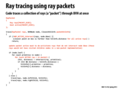
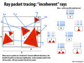
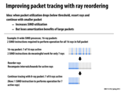
You can visually think of a packet as emerging from your computer screen and heading toward the scene in a frustum that expands outward as it goes. If this frustum misses an object in the scene entirely, then none of the rays in the packet have to be checked for intersection with that object. If any one of them does, then the whole packet descends into the BVH tree bounding the object.
This comment was marked helpful 0 times.

Question Would it be reasonable to think of rays in a packet being implemented as threads in a warp in CUDA? The reason I am not sure is because they seem to share similarities such as executing in SIMD, but a warp is a lower level implementation that the programmer would not necessarily be able to manipulate (unless it's exposed in more recent versions of CUDA) and the packets seem like a higher level abstraction (as the next slide talks about reordering rays). Could this reordering be implemented by assigning work to different threads?
This comment was marked helpful 0 times.

Warps are decently exposed in CUDA. Warps are (currently) always 32 threads. The allocation of threads to warps is well defined. Thread have a thread ID. For 1-dimensional blocks, this is simply threadIdx.x, for 2-dimensional blocks, blockDim.x * threadIdx.y + threadIdx.x and for 3-dimensional blocks, blockDim.x * blockDim.y * threadIdx.z + blockDim.x * threadIdx.y + threadIdx.x. Threads with IDs 0-31 run in the same warp, as do 32-63, etc.
This comment was marked helpful 0 times.

Here is a recent set of Nvidia articles on using BVHs for collision detection with a GPU, which might also be applicable to using BVHs for ray tracing, though I haven't had a chance to read them yet. What are some other good resources on the topic, and in general, where does a GPU come into play in ray tracing, if anywhere?
https://developer.nvidia.com/content/thinking-parallel-part-i-collision-detection-gpu
https://developer.nvidia.com/content/thinking-parallel-part-ii-tree-traversal-gpu
https://developer.nvidia.com/content/thinking-parallel-part-iii-tree-construction-gpu
This comment was marked helpful 0 times.

I think the best approaches to ray tracing on the GPU drop the hard lined ray tracing vs rasterization argument and just take the best approaches to both. For example, rasterization is very well suited to GPUs and so the rays that reach the eyes directly from triangles can be done via rasterization and the global illumination + other special effects can be taken care of by ray tracing (and by ray tracing I also mean the broader approaches of path tracing, photon mapping etc.)
This comment was marked helpful 1 times.

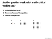
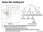
This is the smallest working set we can use since for each cell, we need data from its immediate neighbors.
To get more cache hits, we want to access the grid row-major, and then come to the next row with its neighbors which are above it right on top of it. Since we need data from the neighbors above and below, we would split the processor's local partition into grids of three rows.
This is the processor's entire local partition, not split as in the previous example. We want the processor to be working on a "connected" set of points so that we minimize communication and get more cache hits.
This comment was marked helpful 0 times.